

Internal protection
Surge protectors
Why install them?
Lightning can fundamentally affect us in two ways, either by direct impact or through an overvoltage, so a complete lightning protection system is made up of two systems; an external system against direct impacts and another internal to counteract the effects produced by overvoltages.
We have standardized protectors to protect any installation and/or equipment, we even manufacture protectors tailored to the client and the systems that need to be protected.
Contact us and our technical department will advise you on the most appropriate choice.
SPD · Modular protection systems

Type 1 surge protection devices are recommended in installations where there is a high probability of atmospheric discharges.
| COMPACT PROTECTION DEVICES | ||||
| Reference | Description | Uc. Máx | Iimp | Up |
| AD4-400/240 | Four-polar | 255 V | 100 kA | 1,5 kV |
| AD2-400/240 | Bipolar | 255 V | 100 kA | 1,5 kV |
| AD1-200/240 | Unipolar F-N | 255 V | 50 kA | 1,5 kV |
| AD1-400/240 | Unipolar N-T | 255 V | 100 kA | 1,5 kV |
| Available for all types of land. TT, IT, TN-S and TN-C | ||||
| Standards: IEC 61643-1, EN 61643-11 and UL 1449 | ||||

Type 1 + 2 surge protection devices are installed at the head of the facilities to be protected and combine the characteristics of Type 1 and Type 2.
| COMPACT PROTECTION DEVICES | |||||
| Reference | Description | Uc. Máx (F-N/N-T) | Iimp (L-N) (F-N/N-T) | In | Up |
| BD4-100/240 | Four-pole | 275 V / 255 V | 12,5 / 25 kA | 50 kA | 1,5 / 1,8 kV |
| BD4-100/240 S | Four-pole | 275 V / 255 V | 12,5 / 25 kA | 50 kA | 1,5 / 1,8 kV |
| BD2-100/240 | Bipolar | 275 V / 255 V | 12,5 / 25 kA | 50 kA | 1,5 / 1,8 kV |
| BD2-100/240 S | Bipolar | 275 V / 255 V | 12,5 / 25 kA | 50 kA | 1,5 / 1,8 kV |
| BD1-100/240 | Unipolar | 255 V | 25 kA | 50 kA | 1,8 kV |
| BD4M-50/240 | Four-polar | 275 V / 255 V | 12,5 / 50 kA | 20 kA | 1,5 kV |
| BD2M-50/240 | Bipolar | 275 V / 255 V | 12,5 / 50 kA | 20 kA | 1,5 kV |
| For remote signaling consult reference. | |||||
| Available for all types of land. TT, IT, TN-S and TN-C | |||||
| Standards: IEC 61643-1, EN 61643-11 and UL 1449 | |||||

| PLUG-IN PROTECTION DEVICES | |||||
| Reference | Description | Uc. Máx (F-N/N-T) | Iimp (L-N) (F-N/N-T) | In | Up |
| BD4-60/240 | Four-pole | 275 V / 255 V | 7 / 15 kA | 30 kA | 1,5 / 1,8 kV |
| BD2-60/240 | Bipolar | 275 V / 255 V | 7 / 15 kA | 30 kA | 1,5 / 1,8 kV |
| BV1-60/240 | Unipolar | 275 V | 7 kA | 30 kA | 1,5 kV |
| For remote signaling consult reference. | |||||
| Avaliable for all types of land. TT, IT, TN-S and TN-C | |||||
| Standards: IEC 61643-1, EN 61643-11 and UL 1449 | |||||

| CARTRIDGE FOR PLUG-IN PROTECTION DEVICES | |||||
| Reference | Description | Uc. Máx (F-N/N-T) | Iimp (L-N) (F-N/N-T) | In | Up |
| BD2-60/240 V | Cartridge F-N | 275 V | 7 kA | 30 kA | 1,5 kV |
| BD2-60/240 D | Cartridge N-T | 275 V | 15 kA | 30 kA | 1,8 kV |
| BD4-60/240 V | Cartridge F-N | 275 V | 7 kA | 30 kA | 1,5 kV |
| BD4-60/240 D | Cartridge N-T | 255 V | 15 kA | 30 kA | 1,8 kV |

Type 2 surge protection devices are installed at the head of electrical installations and at secondary power panels. They protect electronic and electrical equipment against transient overvoltages of industrial, atmospheric, and maneuver origin.
| PLUG-IN PROTECTION DEVICES | |||||
| Reference | Description | Uc. Máx | In | I Máx | Up |
| BV1-40/240 | Unipolar | 275 V | 20 kA | 40 kA | 1,2 kV |
| BD2-40/240 | Bipolar | 275 V / 255 V | 20 kA | 40 kA | 1,2 / 1,5 kV |
| BD4-40/240 | Four-pole | 275 V / 255 V | 20 kA | 40 kA | 1,2 / 1,5 kV |
| BV4M-40/240 | Four-pole | 275 V | 20 kA | 40 kA | 1,2 kV |
| BV2M-40/240 | Bipolar | 255 V | 20 kA | 40 kA | 1,2 kV |
| For remote signaling consult reference. | |||||
| Available for all types of land. TT, IT, TN-S and TN-C | |||||
| Standards: IEC 61643-1, EN 61643-11 and UL 1449 | |||||

| PLUG-ON PROTECTION DEVICES | |||||
| Reference | Description | Uc. Máx | In | I Máx | Up |
| BV2-40/240 V | Cartridge F-N | 275 V | 20 kA | 40 kA | 1,2 kV |
| BD2-40/240 D | Cartridge N-T | 275 V | 20 kA | 40 kA | 1,2 kV |
| BV4M-40/240 | Cartridge F-N / N-T | 275 V | 20 kA | 40 kA | 1,2 kV |
| BV2M-40/240 | Cartridge F-N / N-T | 275 V | 20 kA | 40 kA | 1,2 kV |

Type 2+3 surge protection devices are installed at the power supply of the final receivers and combine the characteristics of Type 2 and Type 3.
| PLUG-IN PROTECTION DEVICES | ||||||
| Reference | Description | Uc. Máx | In | I Máx | Up | Uoc |
| BV1-20/240 | Unipolar | 275 V | 10 kA | 20 kA | 1,1 kV | 20 kV |
| BD2-20/240 | Bipolar | 275 V / 255 V | 10 kA | 20 kA | 1,1 / 1,3 kV | 20 kV |
| BD4-20/240 | Four-pole | 275 V / 255 V | 10 kA | 20 kA | 1,1 / 1,3 kV | 20 kV |
| BV2M-20/240 | Bipolar | 275 V | 10 kA | 20 kA | 1,1 kV | 20 kV |
| BV4M-20/240 | Four-pole | 255 V | 10 kA | 20 kA | 1,1 kV | 20 kV |
| For remote signaling consult reference. |
||||||
| Available for all types of land. TT, IT, TN-S and TN-C |
||||||
| Standards: IEC 61643-1, EN 61643-11 and UL 1449 |
||||||

| CARTRIDGES FOR PLUG-IN PROTECTION DEVICES | ||||||
| Reference | Description | Uc. Máx | In | I Máx | Up | Uoc |
| BD2-20/240 V | Cartridge F-N | 275 V | 10 kA | 20 kA | 1,1 kV | 20 kV |
| BD4-20/240 V | Cartridge F-N | 275 V | 10 kA | 20 kA | 1,1 kV | 20 kV |
| BD2M-20/240 V | Cartridge F-N / N-T | 275 V | 10 kA | 20 kA | 1,1 kV | 20 kV |
| BV4M-20/240 V | Cartridge F-N / N-T | 275 V | 10 kA | 20 kA | 1,1 kV | 20 kV |
| BD2-20/240 D | Cartridge N-T | 255 V | 10 kA | 20 kA | 1,3 kV | 20 kV |
| BD4-20/240 D | Cartridge N-T | 255 V | 10 kA | 20 kV | 1,3 kV | 20 kV |

Overvoltage protection devices for protection equipment that work in direct current. They protect photovoltaic equipment against transient overvoltages of atmospheric origin and maneuver.
| PLUG-IN PROTECTION DEVICES | |||||
| Reference | Description | Ucpv | PV In | I Máx | Up |
| BF3-40/600 | Tripolar | 620 Vcc | 20 kA | 40 kA | 2,0 kV |
| BF3-40/1000 | Tripolar | 1060 Vcc | 20 kA | 40 kA | 3,6 kV |
| BF3-40/1500 | Tripolar | 1520 Vcc | 20 kA | 40 kA | 4,0 kV |
| For remote signaling consult reference. | |||||
| Standards: IEC 61643-1, EN 61643-11 and UL 1449 |
|||||

| CARTRIDGES FOR PLUG-IN PROTECTION DEVICES | |||||
| Reference | Description | Ucpv | PV In | I Máx | Up |
| BF3-40/600 V | Cartridge | 620 Vcc | 20 kA | 40 kA | 2,0 kV |
| BF3-40/1000 V | Cartridge | 1060 Vcc | 20 kA | 40 kA | 3,6 kV |
| BF3-40/1500 V | Cartridge | 1520 Vcc | 20 kA | 40 kA | 4,0 kV |

Surge protection devices for data lines protect the electronic equipment of the communication network against any transient overvoltage induced on the data lines. These protectors must be installed as close as possible to the equipment to be protected.
| PROTECTION DEVICES FOR DATA LINES | ||||||
| Reference | Descriptions | Uc. Máx | In | I Máx | Up (L-L / L-T) | IL |
| TD/5-B0 | 1 pair | 6 Vcc | 5 kA | 10 kA | 80/350 V | 500 mA |
| TD/12-B0 | 1 pair | 15 Vcc | 5 kA | 10 kA | 150/350 V | 500 mA |
| TD/24-B0 | 1 pair | 28 Vcc | 5 kA | 10 kA | 200/500 V | 500 mA |
| TD/48-B0 | 1 pair | 60 Vcc | 5 kA | 10 kA | 250/500 V | 500 mA |
| TD/110-A0 | 1 pair | 180 Vcc | 5 kA | 10 kA | 0,5 kV | 500 mA |
| TD/250-A0 | 1 pair | 275 Vcc | 5 kA | 10 kA | 1/0,75 kV | 500 mA |
| Standards: IEC 61643-1 |
||||||
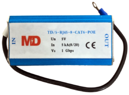
| PROTECTION DEVICES FOR TELEPHONE LINES, ADSL AND ETHERNET | ||||||
| Reference | Description | Uc. Máx | In
(L-L / L-T) |
I Máx
(L-L / L-T) |
Up
(L-L / L-T) |
IL |
| TD/110-RJ11-4 | For telephone line via RJ1 connector | 180 Vcc | 2 kA | 5 kA | 200/500 V | 0,5 A |
| TD/5-RJ45-8-CAT 6 | For Ethernet via RJ45 connector, Cat 6 | 6 Vcc | 2,5 kA | 5 kA | 15/800 V | 0,5 A |
| TD/5-RJ45-8-CAT 6-POE | Ethernet RJ 45, Cat 6
Power Over Ethernet |
6 Vcc
(57 Vcc POE) |
2,5 kA | 5 kA | 25/600 V | 0,5 A |
| Standards: IEC 61643-1 |
||||||

Surge protection devices for coaxial cables protect the electronic equipment associated with the coaxial installation against any type of transient overvoltage induced on the coaxial cables. These protectors must be installed as close as possible to the equipment to be protected.
| PROTECTION DEVICES FOR COAXIAL CABLES | |||||
| Reference | Description | Uc. Máx | I Máx | Impedacia | Up |
| CD-90-B-HH-75 | Type BNC Female – Female | 70 Vcc | 20 kA | 75 Ω | 700 V |
| CD-250-B-HH-75 | Type BNC Female – Female | 200 Vcc | 20 kA | 75 Ω | 700 V |
| CD-90-B-MH-75 | Type BNC Male – Female | 70 Vcc | 20 kA | 75 Ω | 700 V |
| CD-250-B-MH-75 | Type BNC Male – Female | 200 Vcc | 20 kA | 75 Ω | 700 V |
| CD-90-F-HH-75 | Type F Female – Female | 70 Vcc | 20 kA | 75 Ω | 700 V |
| CD-250-F-HH-75 | Type F Female – Female | 200 Vcc | 20 kA | 75 Ω | 700 V |
| CD-90-F-MH-75 | Type F Male – Female | 70 Vcc | 20 kA | 75 Ω | 700 V |
| CD-250-F-MH-75 | Type F Male – Female | 200 Vcc | 20 kA | 75 Ω | 700 V |
| Available in other types of connection and impedance. | |||||
| Standards: IEC 61643-2 | |||||
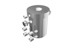
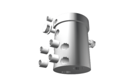
SPU · Unified protection systems
Unified protection systems, also known as SPUs, are made up of multiple redundant protection sets coordinated with each other and designed according to the criteria of maximum discharge capacity and minimum residual voltage. Its design allows the implementation of accessory modules, as well as its adaptation to the needs of each installation, giving priority to its safety and proper functioning.
The SPUs have been designed to ensure the protection of installations against overvoltages of atmospheric and industrial origin, MF/AM harmonics, and peaks associated with micro-interruptions. In addition, the electrical installation will be protected against overvoltages, power outages, and phase asymmetry by adding a PTR4 set. This set is programmable in time and voltage.
- Large discharge capacity for 8/20 µs and 10/350 µs waveforms.
- Residual values close to the voltage of the protected installation.
- Frequency filtering.
- There are 3 or 4 effective and self-coordinated protective sets, each one by itself.
- Eliminates surges between phases, phase-ground, phase-neutral, and neutral-ground.
- Response time of 0.025µs.
- Microinterruptions in the order of milliseconds are eliminated in low power installations.
- Repairable
| MAIN CHARACTERISTICS TO DEFINE THE DIFFERENT RANGES OF SPU SERIES | |||||
| SERIES 4D | SERIES 2D | SERIES 4S | SERIES 2S | SERIES 3F | |
| Installation method | Parallel | Parallel | Series | Series | Parallel |
| Rated voltage (V)(1) | 230/240 | 230 | 230/240 | 230 | 400 |
| Protection against industrial transient overvoltages 8/20 µs | * | * | * | * | * |
| Protection against transient lightning surges 10/350 µs (2) | * | * | * | – | – |
| Protection against permanent overvoltages (3) | * | * | * | – | – |
| Undervoltages protection (3) | * | * | * | – | – |
| Phase asymmetry protection (3) | * | * | * | – | – |
| MF/AF harmonic protection | * | * | * | * | * |
| (1) Available in other voltages on request. | |||||
| (2) According to models. | |||||
| (3) Requires the addition of the PTR4 kit. | |||||

SERIE 2D
Sistemas de protección monofásicos en derivación.

SERIE 4D
Sistemas de protección trifásicos en derivación.

SERIE 4S
Sistemas de protección trifásicos en serie.

SERIE 2S
Sistemas de protección monofásicos en serie.

SERIE DK
Sistemas de protección en derivación para alta tensión.

SERIE TC
Sistemas de protección a líneas de datos y comunicación.
Our protection systems have been designed to protect all types of electrical and electronic installations of any power, especially those that have sensitive electronic devices. With the installation of an SPU, installations are prevented from being affected by: overvoltages, micro-interruptions, harmonics, undervoltages, phase asymmetry, and electromagnetic compatibility.
Given that not all installations are the same, and to protect them effectively, it is necessary to adapt both to their characteristics and to the demands of our client, at MD we offer the possibility of modifying the features of our products. Therefore, any device developed by MD can:
- Adjust to special supply voltages: 500 V, 690 V, etc.
- Modify the IP degree in the installations that require it.
- Increase the energy dissipation capacity in installations subjected to very energetic discharges.
- Increase the frequency filtering capacity.
- Adapt to any type of network: two-phase, three-phase are neutral, IT, TT, etc.
- It incorporates acoustic alarms.
| NOTE |
| If you need any SPD or SPU with different characteristics, contact us and our technical department will advise you on the most appropriate choice. |
Railway protection

We are specialists in the design and manufacture of railway protection devices. Our devices are designed under the criteria of maximum reliability and robustness. We collaborate with engineering companies in the search for solutions to specific problems through the development of personalized devices. The most relevant protection devices designed and developed by MD are:
- Protection of rectifier groups of substations against overvoltages.
- Protection of electronic devices for auxiliary services against overvoltages and MF/AF harmonics.
- Protection of interlocked cabinets against overvoltages, MF/AF harmonics, and overcurrents.
- Protection of signaling circuits against overvoltages.
- Polarized protection devices (DPPo).
- interval downloaders.
- Electrolytic corrosion protection devices.
- Outdoor auto valves.
- Internal auto valves with remote signaling
How can we help you?
Grounding
Grounding
The part responsible for dissipating lightning energy
The ground connection is the part of the system that is responsible for safely dispersing the lightning current. For this reason, it is necessary to take into account some aspects at the time of its installation, since the safety of the entire installation will depend on the correct functioning of the ground connection.
First of all, for the system to function correctly, it is necessary that the value of the ground connection of the lightning rod with a priming device be below 10 ohms.
The layout of the grounding system is also important. The most suitable configuration to obtain the best value with the fewest number of elements is in triangle or goose foot.
In addition, whenever possible, it is convenient to have the earth connections interconnected and, preferably, by means of a spark gap.
Electrodes

Active electrode with moisture exchanger and drainage of ionic compound especially indicated for carrying out grounding in very high resistivity terrain. Includes stainless steel connector for conductors from Ø 8 to 10 mm and flat up to 30 mm.
| Reference | Material | Diameter | Lenght | Form |
| AS500070 | Copper + Composite | 28 mm | 1500 mm | Vertical |
| AS500071 | Copper + Composite | 28 mm | 2000 mm | Vertical |
| AS500080 | Copper + Composite | 50 mm | 1500 mm | Vertical |
| AS500081 | Copper + Composite | 50 mm | 2000 mm | Vertical |
| Complies with: IEC 62305, UL 467, EN 50164, UNE 21186, NFC 17102 and NP 4426 |
||||

Rigid graphite electrode indicated for making earth connections in particularly aggressive terrain. Includes stainless steel connector for conductors from Ø 8 to 10 mm and flat up to 30 mm.
| Reference | Material | Diameter | Length | Drilling |
| AS500040 | Rigid graphite | 50 mm | 400 mm | 2 m |
| AS500041 | Rigid graphite | 50 mm | 800 mm | 2 m |
| Complies with: UNE 21186, NFC 17102 and NP 4426 |
||||

Copper-plated steel electrode for grounding with a high degree of resistance to corrosion.
| Reference | Material | Diameter | Lenght | Covering | Finish |
| AS500101 | Copper plated steel | 14,2 mm | 2 m | 254 microns | Smooth |
| AS500131 | Copper plated steel | 14,2 mm | 2 m | 100 microns | Smooth |
| AS500161 | Copper plated steel | 14,2 mm | 2 m | 254 microns | Threaded |
| Complies with: BS 7430, BS 6651, UL 467, NFPA 780, IEC 62305, EN 50164, UNE 21186, NFC 17102 and NP 4426 | |||||

Stainless steel electrode for grounding. with a high degree of corrosion resistance.
| Reference | Material | Diameter | Length | Finish |
| AS500133 | Stainless steel | 14,2 mm | 2 m | Smooth |
| Complies with: IEC 62305, EN 50164, UNE 21186, NFC 17102 and NP 4426 | ||||
Accessories for electrodes

Accessory for extension and driving of the electrodes.
| Reference | Material | For electrode |
| AS500140 | Bronze / Copper | SMOOTH of Ø 14,2 mm |
| AS500190 | Bronze / Copper | THREADED of Ø 14,2 mm |
| Complies with: UNE 21186, NFC 17102 and NP 4426 | ||

Staples for joining electrodes with grounding conductors.
| Reference | Material | For electrode | For round conductor | For flat conductor |
| AS500330 | Copper | Up to Ø 20 mm | Up to 70 mm2 | Up to 30 mm |
| AS500390 | Brass | Up to Ø 14,2 mm | Up to 70 mm2 | – |
| AS500391 | Bronze | Up to 5/8” | – | – |
| Complies with: UNE 21186, NFC 17102 and NP 4426 | ||||

Connect round conductors to steel constructions. It is possible to connect longitudinal and transverse terminals.
| Reference | Material | For metallic structures | For round conductor |
| AS500380 | Steel | From 5 to 18 mm | Ø 20 mm |
| Complies with: UNE 21186, NFC 17102 and NP 4426 | |||

Accessories for extension and nailing of stainless steel electrodes.
| Reference | Accessories | Material | For electrode |
| AS500250 | Screw | Hardened steel | Ø 16 mm |
| AS500251 | Spike | Stainless steel | Ø 16 mm |
| AS500252 | Nailed point | Stainless steel | Ø 16 mm |
| AS500280 | Nailed point | Galvanized steel | Ø 20 mm |
| Complies with: UNE 21186, NFC 17102 and NP 4426 | |||
Grounding improvers

Totally ecological, non-corrosive, very hygroscopic and fast-acting ionic compound that substantially improves the conductivity of the ground.
| Reference | Material | Weight |
| AS500460 | 3 compounds | 3 kg |
| Complies with: EN 50164, UNE 21186, NFC 17102 and NP 4426 | ||

Plates with connector for conductors recommended as grounding electrodes to obtain a very low resistance in very rocky terrain due to the large surface in contact with the ground.
| Reference | Material | Dimensions | For conductor |
| AS500401 | Cobre | 500 x 500 x 1,5 mm | 6 |
| AS500411 | Cobre | 500 x 500 x 1,5 mm | 8 |
| Complies with: UNE 21186, NFC 17102 and NP 4426 | |||
Inspection pit for grounding


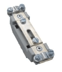
Stainless steel connection bridge for the equipotential bonding of earthing electrodes and round conductors of Ø 8/10 mm and flat conductors up to 30 mm wide.
| Reference | Material | Dimensions | Connections | For inspection pit |
| AS500540 | Stainless steel | 60 x 5 x 196 mm | 6 | AS500512 |
| AS500541 | Stainless steel | 60 x 5 x 242 mm | 8 | AS500513 |
| Complies with: EN 50164, UNE 21186, NFC 17102 and NP 4426 | ||||
Equipotential bonding
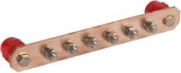
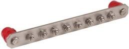
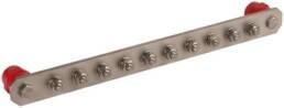
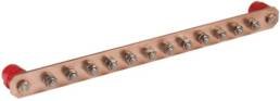
Compensation and equipotentiality bars to be fixed using thermostable, self-extinguishing, halogen-free and UV-resistant insulators. With a connection system using M-10 stainless steel screws, which allows the joining of conductors of different types and sections using suitable connection terminals.
| Reference | Material | Dimensions | connections |
| AS500570 | Copper | 250 x 40 x 5 mm | 6 |
| AS500571 | Copper | 310 x 40 x 5 mm | 8 |
| AS500572 | Copper | 370 x 40 x 5 mm | 10 |
| AS500573 | Copper | 430 x 40 x 5 mm | 12 |
| AS500580 | Stainless steel | 250 x 40 x 6 mm | 6 |
| AS500581 | Stainless steel | 310 x 40 x 6 mm | 8 |
| AS500582 | Stainless steel | 370 x 40 x 6 mm | 10 |
| AS500583 | Stainless steel | 430 x 40 x 6 mm | 12 |
| Complies with: DIN EN 62561-1 | |||

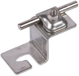
Fixed connection points to connect to the framework of the structure or ground system.
| Reference | Material | Contact plate | Length | Weight | Thread |
| AS500135 | Stainless steel | Ø 80 mm | 190 mm | 217 gr. | M-10 |
| Complies with: UNE 21186, NFC 17102 and NP 4426 | |||||
| NOTE |
| If you need an accessory for grounding with different characteristics, contact us and our technical department will advise you on the most appropriate choice. |
How can we help you?
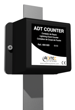
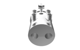
ADT Counter
Measuring devices
ADT Counter
REF. AS600920
THE MOST VERSATILE, COMPLETE AND EASY TO INSTALL LIGHTNING METER.
The ADT Counter counts and records the direct strikes and surges of a lightning protection system.
It is a device that does not intervene in the operation of the protection system, but it is undoubtedly a very important element, because it is the only way of knowing that the system has suffered a lightning strike and that a revision of the system must be carried out to verify that everything is in correct condition and we continue to be protected.
Due to its design and its materials, it is robust, reliable and autonomous. It does not need external power supply and is compatible with any lightning rod

Documents
DATA SHEET
CERTIFICATE
CATALOGUE
Technical data
| Reference | AS600920 |
| Dimensions | 89 x 69 x 45 mm |
| Weight | 285 gr. |
| Minimum threshold current (Itc 8/20 µs) | 1 kA |
| Withstand and counted current (Imcw 10/350 µs) | 100 kA |
| For conductors up to | Ø 15 mm |
| For tapes up to | 60 x 10 mm |
| Operating temperature | From -20ºC to +65ºC |
| Complies with: EN 62561-6, EN 50164-6 and UTE C 17-106 |
|
Installation
- Quick and easy installation.
- It is not necessary to disconnect or section the downspout.
- Valid to install in any type of driver.
The device must be located at any point on the downspout between the protection tube and the mast. It is inserted in the downpipe with less ohmic resistance or, failing that, in the straightest and most direct to ground.
How can we help you?
Comparative
REF. AS900103
- Stainless steel AISI 316L
- Maximum radius of protection: 107 m
- CERTIFICATION OF RESISTANCE TO CORROSION IN SALINE AND HUMID SULFUR ATMOSPHERES
- CERTIFICATION BY REGULATIONS CTE SU8, UNE 21186, NFC 17102, NP 4426
- AAA – Water isolation assurance
- AAA+ – Asurance water isolation in extreme conditions
- EAC – Priming advance stabilization
- DSF – Forced blow deionization
- AAE – Electric arc elongation
- LIFETIME WARRANTY*
REF. AS800103
- Stainless steel AISI 316L
- Maximum radius of protection: 107 m
- CERTIFICATION OF RESISTANCE TO CORROSION IN SALINE AND HUMID SULFUR ATMOSPHERES
- CERTIFICATION BY REGULATIONS CTE SU8, UNE 21186, NFC 17102, NP 4426
- AAA – Water isolation assurance
- __________________________________________ __________________________________________
- EAC – Priming advance stabilization
- __________________________________________
- AAE – Electric arc elongation
- LIFETIME WARRANTY*
REF. AS800010
- Stainless steel AISI 316L
- Maximum radius of protection: 107 m
- CERTIFICATION OF RESISTANCE TO CORROSION IN SALINE AND HUMID SULFUR ATMOSPHERES
- CERTIFICATION BY REGULATIONS CTE SU8, UNE 21186, NFC 17102, NP 4426
- AAA – Water isolation assurance
- __________________________________________ __________________________________________
- __________________________________________
- __________________________________________
- __________________________________________
- LIFETIME WARRANTY*
How can we help you?
Accessories
Accessories
Everything needed for a complete installation according to standards
There are different reasons for installing a complete lightning protection system, but they could be reduced to two fundamentally:
- Having a lightning protection system is the best option to protect people, animals, structures, machinery, and facilities against this natural phenomenon.
- To comply with the regulations that regulate the installation of these systems.
At Aiditec Systems we have all the necessary accessories for the installation of these systems safely and in compliance with current regulations.
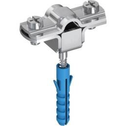
Spark gap

Spark gap for equipotential protection for connection to lightning rods and grounding.
| Reference | Material | Round conductors | Flat conductors |
| AS500550 | Stainless steel | From Ø 8 to 10 mm | Up to 30 mm |
| Complies with: IEC 62305 y EN 50164 | |||
Adaptation pieces
Adaptation piece for joining the lightning rod with the mast and internal connection with the down conductor.
| Reference | Material | Mast | For round | For plate |
| AS700100 | Stainless steel | Ø 45 x 2 mm | 2 x Ø 8/10 mm | – |
| Complies with: UNE 21186, NFC 17102 y NP 4426 | ||||

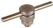
U-Bolt for joining the lightning rod with the mast and with a stainless steel flange for the external connection with the down conductor.
| Reference | Material | Mast | For conductor | For plate |
| AS700150 | Stainless steel | Up to Ø 45 mm | Up to Ø 15 mm | 50 x 5 mm |
| Complies with: UNE 21186, NFC 17102 y NP 4426 | ||||
Mast
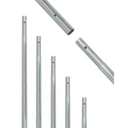
Masts made of galvanized steel or stainless steel (optimal for highly corrosive environments) with a diameter of 45 and a thickness of 2 mm to be attached to buildings or structures with 2 supports (except 8 m masts that are fixed with 3 supports + guys).
| Reference | Material | Sections / Length | Total length (m) |
| AS700229 | Galvanized steel | 1 section / 2 m | 2 |
| AS700231 | Galvanized steel | 2 sections / 2 m | 4 |
| AS700233 | Galvanized steel | 3 sections / 2 m | 6 |
| AS700235 | Galvanized steel | 4 sections / 2 m | 8 |
| AS700270 | Stainless steel | 1 section / 2 m | 2 |
| AS700271 | Stainless steel | 2 sections / 2 m | 4 |
| AS700273 | Stainless steel | 3 sections / 2 m | 6 |
| AS700275 | Stainless steel | 4 sections / 2 m | 8 |
| Complies with: UNE 21186, NFC 17102 y NP 4426 | |||

Masts to be installed on a concrete block embedded in the ground, made of galvanized steel and studied to withstand winds of up to 140 km/h.
| Reference | Length | Sections | Assembly | Base plate dimensions (mm) | Foundation dimensions (cm) |
| AS700306 | 6 m | 2 | Screwed | 400 x 400 x 10 | 80 x 80 x 80 |
| AS700308 | 8 m | 3 | Screwed | 400 x 400 x 10 | 80 x 80 x 80 |
| AS700310 | 10 m | 4 | Screwed | 500 x 500 x 10 | 100 x 100 x 100 |
| AS700312 | 12 m | 5 | Screwed | 500 x 500 x 10 | 100 x 100 x 100 |
| AS700315 | 15 m | 6 | Screwed | 500 x 500 x 10 | 150 x 150 x 150 |
| AS700320 | 20 m | 8 | Welded | 600 x 600 x 10 | 200 x 200 x 200 |
| AS700325 | 25 m | 10 | Welded | 750 x 750 x 12 | 200 x 200 x 200 |
| Complies with: UNE 21186, NFC 17102 y NP 4426 | |||||
Anchors

Anchors for fixing masts up to Ø 45 mm to roofs and flat surfaces.
| Reference | Material | Tube height | Base plate dimensions |
| AS700400 | Galvanized steel | 75 cm | 300 x 300 mm |
| AS700401 | Galvanized steel | 100 cm | 500 x 500 mm |
| AS700602 | Zinc plated steel | 45 cm | 250 x 250 mm |
| AS700603 | Zinc plated steel | 75 cm | 250 x 250 mm |
| Complies with: UNE 21186, NFC 17102 y NP 4426 | |||

Standard anchor to embed or screw. Manufactured in a «U» profile of 20 x 40 x 20 and thickness of 3 mm.
| Reference | Material | Length | Type of fixing |
| AS700624 | Galvanized steel | 20 cm | To screw |
| AS700625 | Galvanized steel | 35 cm | To screw |
| AS700626 | Stainless steel | 50 cm | To screw |
| Complies with: UNE 21186, NFC 17102 y NP 4426 | |||

Light anchor to embed. Manufactured in a «U» profile.
| Reference | Material | Length |
| AS700440 | Galvanized steel | 35 cm |
| AS700441 | Galvanized steel | 50 cm |
| AS700640 | Stainless steel | 35 cm |
| AS700641 | Stainless steel | 50 cm |
| Complies with: UNE 21186, NFC 17102 y NP 4426 | ||

Anchors for parallel and cross fixing of masts up to Ø 45 mm.
| Reference | Material | Length | Type of fixing |
| AS700460 | Galvanized steel | 20 cm | Parallel |
| AS700481 | Galvanized steel | 20 cm | + |
| AS700660 | Zinc plated steel | 20 cm | Parallel |
| AS700681 | Zinc plated steel | 20 cm | + |
| Complies with: UNE 21186, NFC 17102 y NP 4426 | |||

Anchor for welding to structures. Manufactured in a «U» profile of 20 x 40 x 20 mm and thickness of 3 mm.
| Reference | Material | Length |
| AS700500 | Galvanized steel | 35 cm |
| AS700501 | Galvanized steel | 50 cm |
| AS700700 | Zinc plated steel | 35 cm |
| AS700701 | Zinc plated steel | 50 cm |
| Cumple con: UNE 21186, NFC 17102 y NP 4426 | ||

Adjustable anchor made of a 20 x 40 x 20 mm «U» profile and 3 mm thick. Fixation by screws.
| Reference | Material | Regulation |
| AS700540 | Galvanized steel | From 50 to 80 cm |
| Complies with: UNE 21186, NFC 17102 y NP 4426 | ||

Anchors for fixing masts to turrets and lattices. Manufactured in a «U» profile of 20 x 40 and 3 mm thick.
| Reference | Material | Length | For turrets |
| AS700560 | Galvanized steel | 42 cm | Model 180 |
| AS700561 | Galvanized steel | 49 cm | Model 250 |
| AS700562 | Galvanized steel | 60 cm | Model 360 |
| AS700760 | Zinc plated steel | 42 cm | Model 180 |
| AS700761 | Zinc plated steel | 49 cm | Model 250 |
| AS700762 | Zinc plated steel | 60 cm | Model 360 |
| Complies with: UNE 21186, NFC 17102 y NP 4426 | |||
Conductors
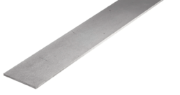
Bare flat conductors are recommended by lightning protection regulations as downstream and ground conductors.
| Reference | Material | Dimensions |
| AS600121 | Tinned copper | 30 x 2 mm |
| AS600181 | Stainless steel | 30 x 2 mm |
| Complies with: IEC 62305, EN 50164, EN 13601, BS 7430, UNE 21186, NFC 17102, NP 4426, AS 1567, BS 6746, BS 2898, BS 6360 and AS 1866 | ||

Bare solid conductors are recommended by lightning protection regulations for use in highly corrosive environments.
| Reference | Material | Dimensions |
| AS600200 | Copper | Ø 8 mm |
| AS600260 | Galvanized steel | Ø 8 mm |
| AS600261 | Galvanized steel | Ø 10 mm |
| Complies with: IEC 62305, EN 50164, EN 13601, BS 7430, UNE 21186, NFC 17102, NP 4426, AS 1567, BS 6746, BS 2898, BS 6360 and AS 1866 | ||

Bare stranded conductors are recommended by lightning protection regulations for use in highly corrosive environments.
| Reference | Material | Dimensions | Wires |
| AS600301 | Copper | 50 mm2 | 19 |
| AS600302 | Copper | 75 mm2 | 19 |
| AS600303 | Copper | 95 mm2 | 19 |
| Complies with: IEC 62305, EN 50164, EN 13601, BS 7430, UNE 21186, NFC 17102, NP 4426, AS 1567, BS 6746, BS 2898, BS 6360 and AS 1866 | |||
Fixings for conductors
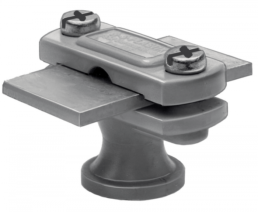
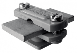
Clamps for fixing flat conductors to buildings and structures. Includes plug and screw.
| Reference | Material | For conductor | Conductor elevation |
| AS600460 | Stainless steel | Up to 30 mm wide | 10 mm |
| AS600461 | Stainless steel | Up to 30 mm wide | 60 mm with extension |
| AS600462 | Stainless steel | Up to 30 mm wide | 110 mm with extension |
| AS600481 | Nylon | Up to 30 mm wide | 25 mm |
| AS600482 | Nylon | Up to 30 mm wide | 40 mm |
| AS600450 | Stainless steel | 30 x 2 | Without extension |
| Complies with: UNE 21186, NFC 17102 and NP 4426 | |||
Staples for fixing round conductors to buildings and structures. Includes plug and screw.
| Reference | Material | For conductor | Conductor elevation |
| AS600560 | Nylon | Ø 7 to 10 mm | 10 mm |
| AS600561 | Nylon | Ø 7 to 10 mm | 60 mm with extension |
| AS600562 | Nylon | Ø 7 to 10 mm | 110 mm with extension |
| AS600580 | Nylon | Ø 7 to 10 mm | 25 mm |
| AS600581 | Nylon | Ø 7 to 10 mm | 40 mm |
| Complies with: UNE 21186, NFC 17102 and NP 4426 | |||

Spacers/extensions for fixing conductors to buildings and structures.
| Reference | Material | Diameter | Length |
| AS600680 | Stainless steel | Ø 25 mm | 50 mm |
| AS600681 | Stainless steel | Ø 25 mm | 100 mm |
| AS600690 | Brass | Ø 25 mm | 50 mm |
| AS600691 | Nylon | Ø 25 mm | 100 mm |
| Complies with: UNE 21186, NFC 17102 and NP 4426 | |||
Supports for conductor fixation
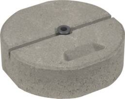
Supports for fixing conductors to flat surfaces.
| Reference | Material | Support | For conductor | Status |
| AS600600 | Polypropylene | Conical | Ø 8 mm | Empty |
| AS600601 | Polypropylene | Conical | Ø 8 mm | Filled |
| AS600620 | Concrete | Block | Ø 8 mm | – |
| Complies with: UNE 21186, NFC 17102 and NP 4426 |
||||
Supports for fixing conductors to tiles.
| Reference | Material | For conductor | Type |
| AS600640 | Stainless steel | From Ø 6 to 11 mm | Adjustable 170/240 mm |
| AS600641 | Stainless steel | To Ø 8 mm | Extensible 170/280 mm |
| AS600642 | Stainless steel | From Ø 6 to 10 mm | Adjustable 120/240 mm (for ridge cap) |
| AS600643 | Copper | From Ø 6 to 10 mm | Adjustable 120/240 mm (for ridge cap) |
| AS600660 | Stainless steel | To Ø 8 mm | Pressure. For 8/10 mm thickness |
| AS600661 | Stainless steel | To Ø 8 mm | Pressure. For 15/20 mm thickness |
| AS600670 | Stainless steel | From Ø 6 to 10 mm | For sandwich type roofs |
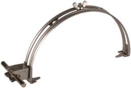
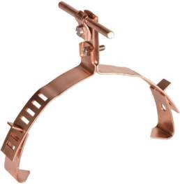
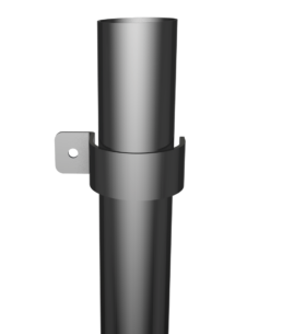
| AS600700 | Stainless steel | Not include fixing | For pipes from Ø 60 to 150 mm |
| AS600720 | Stainless steel | Not include fixing | For pipes from Ø 60 to 150 mm |
| AS600740 | Copper | Not include fixing | For pipes from Ø 60 to 150 mm |
| Complies with: EN 50164, UNE 21186, NFC 17102 and NP 4426 |
|||

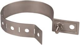
Support for stainless steel strip
| Reference | Material | Screw | For conductor | Tensioning strap |
| AS600750 | Stainless steel | M8 – 10 mm | Ø 8 mm | 15 x 0,4 mm |
| Complies with: UNE 21186, NFC 17102 and IEC 62305 | ||||
Joints and connections

Universal connector for round stainless steel conductors with multiple connection methods.
| Reference | Material | Dimensions | For conductor | Screw |
| AS600841 | Stainless | 40 x 40 x 40 mm | For Ø 8 to 10 mm | M-10 x 40 mm |
| Complies with: IEC 62305, EN 50164, UNE 21186, NFC 17102 and NP 4426 |
||||

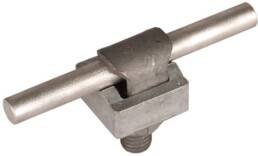
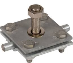
Cross connector for flat and round conductors and test link.
| Reference | Material | For conductor | For flat | For electrode |
| AS600823 | Stainless steel | Up to Ø 10 mm | Up to 30 x 3 mm | Up to Ø 17 mm |
| Complies with: IEC 62305, EN 50164, UNE 21186, NFC 17102 and NP 4426 |
||||

T-connector for round conductors.
| Reference | Material | For conductor |
| AS600806 | Copper | From Ø 8 to 10 mm |
| AS600845 | Galvanized steel | From Ø 8 to 10 mm |
| Complies with: IEC 62305, EN 50164, UNE 21186, NFC 17102 and NP 4426 |
||

Linear connector for round conductors.
| Reference | Material | For conductor |
| AS600804 | Copper | Up to Ø 10 mm |
| AS600824 | Stainless steel | Up to Ø 10 mm |
| Complies with: IEC 62305, EN 50164, UNE 21186, NFC 17102 and NP 4426 |
||

Parallel connector for round conductors.
| Reference | Material | For conductor |
| AS600844 | Copper | From Ø 7 to 10 mm |
| Complies with: IEC 62305, EN 50164, UNE 21186, NFC 17102 and NP 4426 |
||

Gutter connector for round conductors.
| Reference | Material | For conductor |
| AS600821 | Stainless steel | From Ø 6 to 10 mm |
| Complies with: IEC 62305, EN 50164, UNE 21186, NFC 17102 and NP 4426 |
||

Bimetallic connector with an intermediate plate for flat and round conductors.
| Reference | Material | For conductor | For flat |
| AS600870 | Cu / Fe | From Ø 8 to 10 mm | – |
| AS600871 | Cu / Fe | From Ø 8 to 10 mm | Up to 30 mm |
| Complies with: IEC 62305, EN 50164, UNE 21186, NFC 17102 and NP 4426 |
|||
KS type connector for round conductors.
| Reference | Material | For conductor |
| AS600847 | Brass | From Ø 6 to 10 mm |
| AS600826 | Brass | From Ø 6 to 10 mm |
| AS600808 | Brass | From Ø 6 to 10 mm |
| Complies with: IEC 62305, EN 50164, UNE 21186, NFC 17102 and NP 4426 |
||
Other accessories
Tube for the mechanical protection of the down conductor of the protection system.
| Reference | Material | Length | For conductor | For flat |
| AS600950 | Galvanized steel | 2 m | Up to Ø 15 mm | Up to 30 mm |
| AS600951 | Stainless steel | 2 m | Up to Ø 15 mm | Up to 30 mm |
| AS600952 | Cross-linked polyethylene | 2 m | Up to Ø 15 mm | Up to 30 mm |
| Complies with: IEC 62305, EN 50164, UNE 21186, NFC 17102 and NP 4426 |
||||

Rain protector to prevent the passage of water on roofs or flat surfaces where spikes or masts are embedded.
| Reference | Material | Dimensions | For spikes or masts |
| AS600965 | Neoprene | 115 x 115 x 60 mm | Up to Ø 50 mm |
| Complies with: UNE 21186, NFC 17102 and NP 4426 |
|||

Fastening and tensioning of masts by means of steel winds to prevent falls due to the effect of the wind.
| Reference | Material | Cable section | Length |
| AS700352 | Stainless steel | Ø 3 mm | 50 m |
| Complies with: UNE 21186, NFC 17102 and NP 4426 |
|||

Non-flammable insulated cable to ensure systems work in extreme conditions.
| Reference | Material | Section | Type of coating |
| AS600306 | Copper | 50 mm2 | Flame retardant |
| Complies with: UNE 21186, NFC 17102 and NP 4426 |
|||

Flexible metal tube for cable protection.
| Reference | Material | Section | Type of coating |
| AS600752 | Steel | Ø 16 mm | PVC |
| Complies with: UNE 21186, NFC 17102 and NP 4426 |
|||
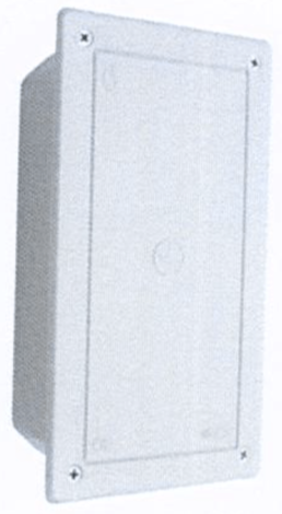
Sectionalizing box for testing grounding resistance.
| Reference | Material | Dimensions | Type of coating |
| AS600401 | Polycarbonate + ABS | 95 x 145 x 75 mm | Copper |
| Complies with: UNE 21186, NFC 17102 and NP 4426 |
|||

Cross-linked polyethylene protection tube against metallic shocks.
| Reference | Material | Diameter | Section | Length | Weight |
| AS600951 | Crosslinked polyethylene 3 mm | Ø 8 – 10 mm | 50 – 70 mm2 | 2000 mm | 728 gr. |
| AS600960 | Crosslinked polyethylene 3 mm | Ø 8 – 10 mm | 50 – 70 mm2 | 2500 mm | 910 gr. |
| Complies with: UNE 21186, NFC 17102 and NP 4426 |
|||||
| NOTE |
| If you need an accessory with different characteristics, contact us and our technical department will advise you on the most appropriate choice. |
How can we help you?
AS TESTER PRO
Measuring devices
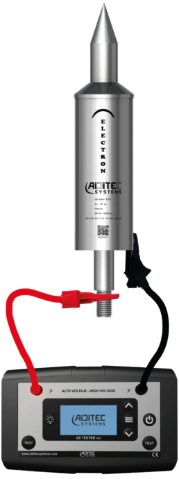
AS TESTER PRO
REF. AS600999
LIGHTNING ROD TESTER WITH PRIMING DEVICE
The AS TESTER PRO is a high-tech portable measurement device that performs an automatic and complete test of the operation of lightning rods with a priming device. It is valid for all ESEs manufactured by Aiditec Systems, S.L.

DOCUMENTS
DATA SHEET
CATALOGUE
TECHNICAL DATA
| Reference | AS600999 |
| Dimensions | 145 x 95 x 35 mm |
| Weight | 288 gr. |
| Maximum output voltage | 3000 V |
| Lightning rod ignition test | 0.3 mA ± 2% |
| Autonomy | 1000 Test |
| Battery | 3,7 V / 1800 mAh |
| Operating temperature | From -20ºC to +65ºC |
| Complies with: EN 62561-6, EN 50164-6 y UTE C 17-106 |
|
FUNCTIONING
- Connect the cables to the connection terminals of the tester
- Connect the lightning rod clamps in the test position, as indicated in the connection diagram regardless of bipolarity.
- Press the power button.
- Select “New Test”.
- Simultaneously press the two TEST buttons to start the cycle.
- Wait a few seconds while the tester performs the test.
The measurement must always be made between 2 existing potentials in all lightning rods with priming devices (ESE):
- ATMOSPHERIC POTENTIAL (Body and tip)
- EARTH POTENTIAL* (axis)
*If the measurement is made with the lightning rod installed, the connection to ground potential can be made on the mast or the downpipe, since both elements would be attached to the axis of the lightning rod.
- Do not touch the lightning rod at the time of testing.
- This equipment produces high voltage. Handle the alligator clips correctly.
- It is necessary to press the test buttons with both hands.
- Avoid testing in stormy conditions.
| TEST OK | Test successful |
| TEST FAILED | Test failed |
| OPEN CIRCUIT | Open circuit >> ESE is faulty |
| SHORT CIRCUIT | Short circuit >> ESE has a short circuit or low resistive value |
| LEAKAGE CORRENT | Leak current >> ESE has a current leak |
| OUT OF RANGE | Out of range >> ESE works at voltages outside those specified |
The AS TESTER PRO lightning rod tester only guarantees the proper functioning of the priming device but not the physical integrity of the lightning rod, so a positive result in a lightning rod that has suffered physical damage does not mean that it maintains its condition. level of coverage, since this does not depend only on the priming device, but also on physical parameters, so to guarantee the level of coverage, a visual inspection of the physical integrity of the lightning rod is also required.
How can we help you?
Measuring devices
Measuring devices
The importance of choosing a good measuring device
Lightning protection systems must ensure optimal and safe operation at all times, so it is necessary to carry out periodic checks.
Measurement devices are essential elements for this correct control and maintenance, helping to prolong the life of these systems and complying with the parameters established by regulations.
Our devices have been designed and developed with the highest quality standards to ensure the proper functioning of the lightning protection installation.
Our devices
The AS TESTER PRO is a high-tech portable measurement device that performs an automatic and complete test of the operation of lightning rods with a priming device. It is valid for all ESEs manufactured by Aiditec Systems, S.L.
| Reference | AS600999 |
| Dimensions | 145 x 95 x 35 mm |
| Weight | 288 gr. |
| Maximum output voltage | 3000 V |
| Lightning rod ignition test | 0.3 mA ± 2% |
| Autonomy | 1000 Test |
| Battery | 3,7 V / 1800 mAh |
| Operating temperature | From -20ºC to +65ºC |
| Complies with: EN 62561-6, EN 50164-6 y UTE C 17-106 |
|
The ADT Counter counts and registers the direct impacts and surges of a lightning protection system. Due to its design and materials, it is robust, reliable and autonomous. It does not need an external power supply and is compatible with any lightning rod.
| Reference | AS600920 |
| Dimensions | 89 x 69 x 45 mm |
| Weight | 285 gr. |
| minimum threshold current (Itc 8/20 µs) | 1 kA |
| Withstand and counted current (Imcw 10/350 µs) | 100 kA |
| For round conductor up to | Ø 15 mm |
| For flat conductor up to | 60 x 10 mm |
| Operating temperature | From -20ºC to +65ºC |
| Complies with: EN 62561-6, EN 50164-6 and UTE C 17-106 |
|
Other accessories for a complete installation
How can we help you?
Passive rods
Passive rods
The simplest protection
Passive rods or Franklin rods are the most common and simple lightning rods. These can be used as the only sensor element or be part of passive protection systems, complementing the protection in conductive meshes (Faraday cages).
Franklin rods do not perform any special action during the electrical storm process, the protection of these points is based on the position of the rods, the morphology, material, and the physical reaction that takes place in the electrostatic field.
Types of passive rods

Franklin rods for protection against lightning. It can be used as a sensor element or be part of passive protection systems. Includes a brass adapter piece for Ø 45 mm mast and internal connection with round conductor Ø 8/10 mm (50/70 mm2)
| Reference | Material | Model | Dimensions (mm) |
| AS700010 | AISI 304 | Multiple Franklin rod | 1 x (Ø 16 x 170) + 3 x (Ø 8 x 65) |
| AS700020 | AISI 304 | Simple Franklin rod | Ø 16 x 170 |
| Complies with: UNE 21186, NFC 17102 y NP 4426 | |||

They are integrated directly into the adaptation piece. It can be used as the only sensor element or be part of passive protection systems, complementing the protection in conductive meshes (Faraday cages).
| Reference | Material | Dimensions (mm) | Thread |
| AS500602 | Cooper | Ø 16 x 500 | Exterior M-16 |
| AS500603 | Cooper | Ø 16 x 1000 | Exterior M-16 |
| AS500680 | AISI 304 | Ø 16 x 500 | Exterior M-16 |
| AS500681 | AISI 304 | Ø 16 x 1000 | Exterior M-16 |
| AS500684 | AISI 304 | Ø 16 x 500 | Exterior M-16 |
| AS500685 | AISI 304 | Ø 16 x 1000 | Exterior M-16 |
| Complies with: IEC 62305 y EN 50164 | |||

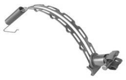
Self-supporting rod with a hinged tripod made of galvanized steel and possibility of adjustment of up to 10º of inclination. Dimensioned to withstand winds of up to 145 km/h. They include concrete counterweights, roof protection plates, and connection clip for Ø 6/10 mm round conductor.
| Reference | Material | Height | Necessary space | Counterweight |
| AS500760 | Galvanized steel and aluminum | 4,5 m | 118 x 132 cm | 3 |
| AS500761 | Galvanized steel and aluminum | 5,5 m | 118 x 132 cm | 6 |
| AS500762 | Galvanized steel and aluminum | 6,5 m | 249 x 283 cm | 6 |
| AS500763 | Galvanized steel and aluminum | 7,5 m | 118 x 132 cm | 6 |
| AS500764 | Galvanized steel and aluminum | 8,5 m | 118 x 132 cm | 9 |
| Complies with: EN 50614, UNE 21186, NFC 17102 y NP 4426 | ||||
ACCESSORIES FOR PASSIVE RODS
Supports for fixing passive rods.
| Reference | Material | Dimensions | Fixing |
| AS500700 | Galvanized steel | 70 x 70 x 70 mm | Internal thread M-10 |
| AS500720 | Concrete | Ø 337 X 90 mm | Internal thread M-16 |
| AS500721 | Concrete | Ø 240 x 90 mm | Internal thread M-16 |
| Complies with: UNE 21186, NFC 17102 y NP 4426 | |||

Roof protection plate when using the concrete support.
| Reference | Material | Dimensions (mm) | Thread |
| AS500730 | Ethylene-vinyl acetate copolymer (EVA) | Ø 370 x 10 mm | Exterior M-16 |
| AS500731 | Ethylene-vinyl acetate copolymer (EVA) | Ø 280 x 10 mm | Exterior M-16 |
| Complies with: IEC 62305 y EN 50164 | |||
How can we help you?
ELECTRON E15
ADVANCE+
SIGMA+
Electron E15
Lightning rod with priming device
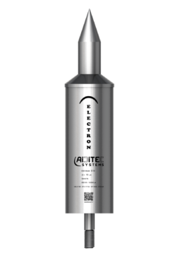
ELECTRON E15
Due to its small size and incredible performance, the ELECTRON E15 lightning rod with priming device (PDC) is perfect for protecting structures and small areas such as towers, antennas, or single-family homes. This device has successfully passed the tests based on the UNE 21186, NFC 17102, and NP 4426 standards for lightning rods with a priming device:
☑️ DIMENSIONALS
Ensures that the dimensions are normalized.
☑️ SALT FOG AND SULFUROUS HUMID ATMOSPHERE
Certifies resistance in corrosive environments.
☑️ CURRENT (200kA – 10/350 µs)
It guarantees the operation after several impacts.
☑️ ADVANCE IN PRIMING
Guarantees the protection radius.
DOCUMENTS
DATA SHEET
CERTIFICATE
CATALOGUE
TECHNICAL DATA
As a result of the research carried out and the R&D projects developed, the ELECTRON E15 lightning rod incorporates the following new technologies:
☑️ AAA – WATER INSULATION ASSURANCE
It allows the ESE electrodes to be isolated, maintaining their potential difference at all times in extreme rain conditions due to electron displacement. By having a dual-energy block, the load of the main system is ensured.
| Material | Stainless steel AISI-316L |
| Weight | 1,8 kg |
| Withstand current | 200 kA – wave 10/350 µs |
| Operating temperature | From -40ºC to +130ºC |
| Metric | Thread M-16 x 2 |

The installation of the PDC ELECTRON E15 must be carried out following the indications of the Technical Building Code (CTE) and standards UNE 21186, NFC 17102 and NP 4426 «Protection against lightning: lightning rod with priming device». See installation guide
All models of the ESE ELECTRON E15 have successfully passed the tests based on current regulations. We certify the following lead time:
| REF. | Model | ∆T Certificate |
|---|---|---|
| AS800010 | ELECTRON E15 | 15 µs |
The radius of protection of the ESE ELECTRON E15 for a height of 6 meters in relation to the area to be protected.
| REF. | Model | Protection level |
|||
|---|---|---|---|---|---|
| I | II | III | IV | ||
| AS800010 | ELECTRON E15 | 30 | 35 | 45 | 50 |
All ESE ELECTRON E15s carry an INTERNATIONAL LIMITED LIFETIME WARRANTY against all manufacturing defects. Learn more about our product warranty at: www.aiditecsystems.com/warranty
How can we help you?
SIGMA+
ADVANCE+
SIGMA+
Electron E15
Lightning rod with priming device
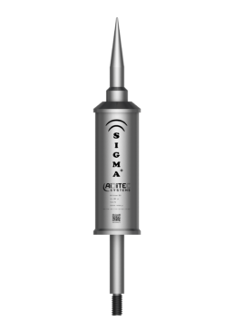
SIGMA+
The SIGMA+ priming device (ESE) lightning rod is an incredibly effective and highly competitive premium protection system. This device has successfully passed the tests based on the UNE 21186, NFC 17102, and NP 4426 standards for lightning rods with a priming device:
☑️ DIMENSIONALS
Ensures that the dimensions are normalized.
☑️ SALT FOG AND SULFUROUS HUMID ATMOSPHERE
Certifies resistance in corrosive environments.
☑️ CURRENT (200kA – 10/350 µs)
It guarantees the operation after several impacts.
☑️ ADVANCE IN PRIMING
Guarantees the protection radius.
DOCUMENTS
DATA SHEET S1
DATA SHEET S2
DATA SHEET S3
CERTIFICATE S1
CERTIFICATE S2
CERTIFICATE S3
CATALOGUE
TECHNICAL DATA
As a result of the research carried out and the R&D projects developed, the ADVANCE+ lightning rod incorporates the following new technologies:
☑️ EAC – STABILIZATION OF ADVANCE IN PRIMING
The dual-energy block allows achieving a maximum deviation of 5% in the advance time based on the product certification regulations.
☑️ AAA – WATER INSULATION ASSURANCE
It allows the PDC electrodes to be isolated, maintaining their potential difference at all times in extreme rain conditions due to electron displacement. By having a dual-energy block, the load of the main system is ensured.
☑️ AAE- ELECTRICAL ARC LENGTH
It avoids the deposition of highly conductive carbon on the PDC electrodes, maintaining its potential difference and avoiding self-discharge of the energy block.
| Material | Stainless steel AISI-316L |
| Weight | 2,2 kg |
| Withstand current | 200 kA – wave 10/350 µs |
| Operating temperature | From -40ºC to +130ºC |
| Metric | Thread M-16 x 2 |

The installation of the ESE SIGMA+ must be carried out following the indications of the Technical Building Code (CTE) and standards UNE 21186, NFC 17102, and NP 4426 «Protection against lightning: lightning rod with priming device». See installation guide
All ESE SIGMA+ models have successfully passed the tests based on current regulations. The results of the laboratory test were much higher, but by regulation, we certify the following advance times:
| REF. | Model | ∆T Certificate |
|---|---|---|
| AS800101 | SIGMA+ S1 | 25 µs |
| AS800102 | SIGMA+ S2 | 45 µs |
| AS800103 | SIGMA+ S3 | 60 µs |
The radius of protection of the ESE SIGMA+ for a height of 6 meters in relation to the plane to be protected.
| REF. | Model | Protection level |
|||
|---|---|---|---|---|---|
| I | II | III | IV | ||
| AS800101 | SIGMA+ S1 | 40 | 50 | 55 | 65 |
| AS800102 | SIGMA+ S2 | 65 | 70 | 80 | 90 |
| AS800103 | SIGMA+ S3 | 80 | 87 | 97 | 107 |
All SIGMA+ ESEs carry an INTERNATIONAL LIMITED LIFETIME WARRANTY against all manufacturing defects. Learn more about our product warranty at: www.aiditecsystems.com/warranty