

Installation of a lightning rod
Installing a lightning rod
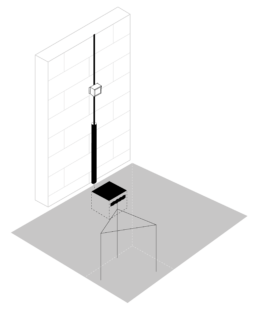
Basic installation guide for an external lightning protection system
The installation of a lightning protection system must always be carried out by specialized technical personnel and in compliance with all the requirements established in current regulations.
The lightning rods with priming device (ESE) will be located at the highest points of the structure, taking into account the location of the ground connections and that the path of the down conductor is as short and rectilinear as possible while avoiding the proximity of electrical, telephone, data lines, etc… and their intersection with them.
The tip of the lightning rod must be located at least 2 meters above any element that is within the area it protects, including antennas, cooling towers, roofs, tanks, etc.
There are 4 levels of protection depending on the probability of impact and the consequences derived from it. To identify the appropriate level of protection in each case, it is necessary to calculate the risk index determined in the UNE 21186, NFC 17102 and NP 4426 standards.
Nature
Down conductors can be flat bars, flat braid, braided, or round cable.
| Material | Remarks | Dimensions |
| Bare or tinned electrolytic cooper | Recommended for its good electrical conductivity and resistance to corrosion | Flat bar 30 x 2 mm Flat braid 30 x 3,5 mm Braided cable 50 mm2 Round Ø 8 mm |
| Stainless steel 18/10, 304 | Recommended in certain corrosive environments | Flat bar 30 x 2 mm Round Ø 8 mm |
| Aluminum A 5/L | It must be used on aluminum surfaces (such as railings, for example) | Plate 30 x 3 mm Round Ø 10 mm |
Situation of down conductor
- They will be located outside the structure.
- When it is impossible to make a downpipe from the outside, the conductors may go inside an insulating and non-flammable tube with a minimum section of 2000mm2 intended for this purpose. In any case, the conditions of proximity must be respected.
- Internal down conductors reduce the effectiveness of the lightning protection system, increase the risk of overvoltage penetration and make it difficult to verify the installation and its maintenance.
Number of down conductors
According to CTE SU8:
- At least one downpipe for each lightning rod with a priming device (ESE).
- A minimum of two downspouts when:
- The horizontal projection of the conductor is greater than its vertical projection.
- The height of the structure is greater than 28 meters.
- Equipotential connections will be made between the shunts at ground level and every 20 meters.
According to UNE 21186 / NFC 17102:
- Each PDC will be connected to the ground by 2 downspouts.
- 4 down conductors will be necessary for buildings higher than 60 meters.
- They will be located whenever possible in the 4 corners of the building.
Path of the down conductor
- The route will describe the shortest, rectilinear and direct path to land, avoiding ski lifts greater than 40 cm with a slope equal to or greater than 45º.
- The radii of the curves must be greater than 20 cm.
- Changes in direction will not be less than 90º.
- When choosing the route, it is necessary to avoid proximity to electrical, telephone, data lines… and its crossing with them.
- When the crossing cannot be avoided, the conduit must be located inside a metallic shield that extends 1 meter to each part of the crossing, and the shield must be joined to the downspout.
Fixing the down conductor
For fixing the down conductors, 3 fixings per meter will be taken as a reference.
Lightning strike counter ADT Counter
The ADT Counter lightning strike counter must be installed on the most direct down conductor to the ground.
Protection
- Mechanical: Each down conductor must be protected against possible mechanical shocks by means of a protection tube up to a height greater than 2 meters from the ground.
- Against contact voltages: Insulation of the exposed down conductors using 3 mm thick cross-linked polyethylene.
Safety distances
According to CTE SU8:
- Safety distance (m) = 0.1 x L*
- Safety distance to external gas pipes ≥ 5 meters.
*L = vertical distance from the point where the proximity is considered to the earth connection of the nearest metal mass or equipotential bonding.
According to UNE 21186 / NFC 17102:
- Safety distance for 1 downpipe (m) = 0,16 x L*
- Safety distance for 2 downspouts (m) = 0,08 x L*
- Safety distance for 4 downspouts (m) = 0,04 x L*
*L = length of the down conductor from the point where the separation distance is considered to the point where the nearest equipotential point is located.
Equipotential joints
When it is not possible to respect the minimum safety distances, the equipotential bonding will be carried out:
- Through equipotential conductors.
- Through equipotential surge protection devices.
Metallic elements, including antennas, must be bonded to the system equipotential, preferably with a spark gap.
- Unless it is absolutely impossible, the ground connections must be oriented towards the outside of the building.
- An earth connection will be made for each down conductor.
- The union of vertical rods with a minimum total length of 6 meters is recommended, arranged in a triangle and spaced by a distance at least equal to their buried length and joined together with a conductor buried in a trench of at least 50 meters. cm deep.
- The value of the resistance of the ground connections must be as low as possible and always less than 10 Ω. When it is not possible to achieve these values, 160 meters of the buried electrode must be installed for protection level I or 100 meters for the rest of the protection levels, provided that the length of each vertical or horizontal element does not exceed 20 meters.
- Each ground connection will have a register box and a sectioning element.
- Measurements will always be made in isolation from any other conductive element.
Safety distances
The grounding elements of the lightning rods must be distant, in the worst case, 5 meters from any buried metallic or electrical conduit.
Equipotential joints
- All ground connections must be connected to each other and to the general ground connection of the building.
- The grounding of the building must be equipotential connected to the grounding of the lightning protection system by means of spark gaps.
- The interconnection with the earth circuit will be made at the bottom of the excavation, directly at the foot of each downspout by means of a device that allows disconnection and that is located in an inspection register that bears the earth symbol.
How can we help you?
Webinars
Webinars
Free online training on lightning protection
From Aiditec Systems we invite you to attend our free webinars where you can learn everything you need on specific topics related to protection against lightning and surges, external and internal protection, and how to correctly protect, according to regulations, buildings, single-family homes, ATEX zones, photovoltaic plants and installations that are sensitive to this meteorological phenomenon.

Telecommunications
In this free webinar from Aiditec Systems, we will learn how to protect ourselves against the damage caused by atmospheric discharges. With an approximate duration of about 30-45 minutes, we will see the external protection and the internal protection.
Mining
We give you the opportunity to attend the free webinar on Lightning Protection Systems in Mining. It will explain how to protect people, goods, and equipment, in areas of large open spaces, from the consequences of atmospheric discharges.
Where the protection against direct lightning strikes, the importance of equipotential bonding and a good grounding system, as well as the design of protection against overvoltages, will be explained.
Internal protection
Online training on internal protection against lightning and surges with products from Aiditec Systems and MD Equipos Tecnológicos.
We will learn how to protect facilities and equipment internally, we will know the regulations and we will show you our online tool for the selection of protectors. In addition, an expert in protection against overvoltages from MD Equipos Tecnológicos will resolve all his doubts.
Renewable energy
Online training on protection against lightning and surges that may be caused by lightning strikes or maneuvers in the electrical network.
We know the importance of having a good grounding system that helps to dissipate the effects of lightning and surges. In addition, we know the regulations that contemplate lightning protection and how to carry out risk calculations according to these international regulations.
Exothermic welding AIDIWELD+PRO
In this seminar, we will see how to carry out a grounding installation with AidiWled+Pro exothermic welding. The importance of making quality connections with exothermic welding and guaranteeing a resistivity value of the ground over time.
External protection
Online training on lightning protection systems with ADVANCE+, SIGMA+, and ELECTRON E15 lightning rods with priming device.
We will see how to protect an installation from the effects of lightning and what elements make up a lightning protection system. In addition, we will see the regulations that contemplate lightning protection and how to carry out risk calculations according to these international regulations.